Greetings!
The milestone 2 report will be divided into 2 parts,
this is a part 1.
Contents:
Part 1:
Why GNS3?
Device management in GNS3
Part 2:
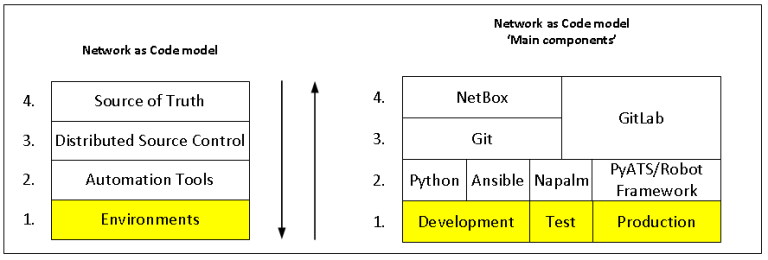
NetBox
GitLab
Ubuntu WS
If you have not read the ‘Introduction’ post, it is a good starting point to understand what I will talk about.
1. Why GNS3?
I use GNS3 in my project because it has the essential functionality out of the box (by default), supports many vendors. It is easy to add all device’s images. Also, It has a Client-server architecture, and Wireshark.
In order not to reinvent the wheel and write about the same things, here are links to useful resources which are helped me:
GNS3: vASA
GNS3: Cisco IOSvL2
GNS3: Juniper vSRX 17.3
PART 1:
PART 2:
GNS3: VyOS
https://wiki.vyos.net/wiki/VyOS_on_GNS3
Also, GNS3 has the feature of export and import projects.
For example, I have built the topology of an enterprise virtual network in Dev. environment and I can easily export the project and import to other environments such as test and prod, in order not to add and connect devices again and again. (time saver)
GNS3: Portable projects
The logical diagram of GNS3 infrastructure in my project:
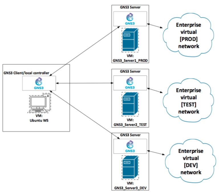
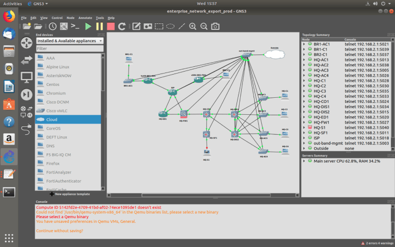
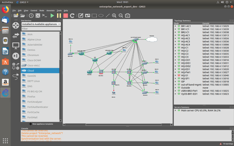
The enterprise virtual [PROD] network in GNS3:
(VM: GNS3_Server1_PROD)
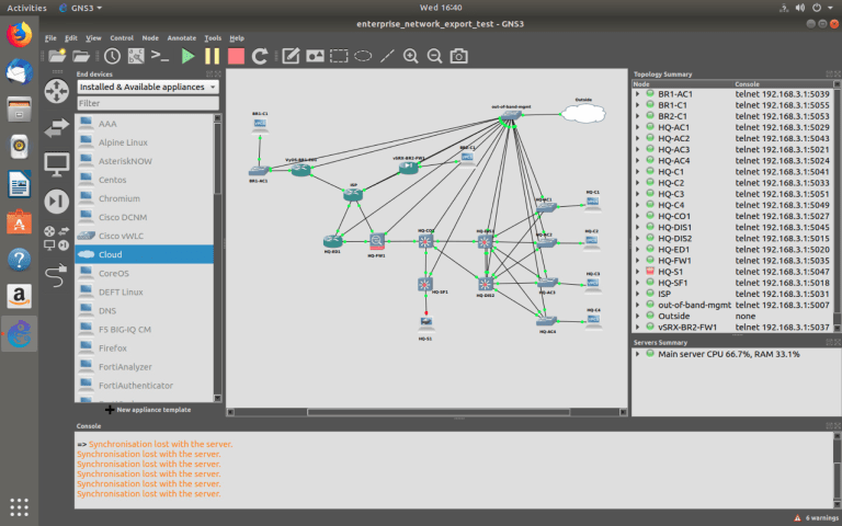
The enterprise virtual [TEST] network in GNS3:
(VM: GNS3_Server2_TEST)
The enterprise virtual [DEV] network in GNS3:
(VM: GNS3_Server3_DEV)
It may seem like they all the same, yes and no because I am using the identical network topology on the three different GNS3 servers which simulate environments.
In reality, the virtual physical topology will be different from the real physical, for example, other physical interfaces.
It is hard to build identical environments. It always depends on …
2. Device management in GNS3
To configure virtual network devices, I use the out-of-band management approach. In short, a dedicated management interface on each device that is separating management traffic from user traffic.
Since the company’s network is virtual, it will be easier to interact with devices. In the real world, of course, everything can be different.
In the screenshots above, you can see ‘out-of-band-mgmt’ vSW (virtual switch) to that all devices are connected.
The L1 (physical) diagram of the enterprise virtual network in GNS3 environments:
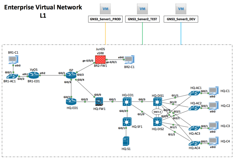
Each environment has a separate MGMT network:
PROD – 192.168.2.0/24
TEST – 192.168.3.0/24
DEV – 192.168.4.0/24
From the ‘Ubuntu WS’ virtual machine, I communicate with the prod/test/dev environments.
How does the interaction occur?
In the real world,
Usually when a new device is purchased that device has the default configuration (factory settings), and the initial configuration performs using a special cable and dedicated port.
For example, a console port and rollover cable.
In the virtual world,
I just click on the device (in GNS3) and that opens a terminal connection (an emulation as if I was connected using a console cable).
Two worlds are similar when I need to configure another way to connect to these devices, such as SSH. Also, add users, configure IP addresses.
In general, do basic settings, so later in a relaxed atmosphere (sometimes not) to continue configuration.
In reality (maybe sometimes) no one will go with a laptop to the server room (usually cold) or drive across the entire city to the data center to change something on the device.
In my case, I did a basic setup on all devices in all environments.
Examples of the basic configuration:
Cisco
vrf definition Mgmt-intf
 !
 address-family ipv4
 exit-address-family
 !
 address-family ipv6
 exit-address-family
!
interface GigabitEthernet0/0
 no switchport
 description MGMT
 vrf forwarding Mgmt-intf
 ip address 192.168.2.100 255.255.255.0
 no shut
!
ip route vrf Mgmt-intf 0.0.0.0 0.0.0.0 192.168.2.254
!
hostname HQ-AC1
enable secret cisco
ip domain name nac.local
username cisco privilege 15 secret cisco
crypto key generate rsa label SSH_KEY modulus 2048
ip ssh version 2
line vty 0 4
logging synchronous
login local
transport input ssh
!
line con 0
logging synchronous
!
ip scp server enable
!
no ip domain lookup
!
do wr
!
Juniper
edit

set system root-authentication plain-text-password

set system host-name vSRX-BR2-FW1

set interfaces fxp0 unit 0 family inet address 192.168.2.113/24

set system services ssh authentication-order password

set system services ssh protocol-version v2

set system login user cisco class super-user authentication plain-text-password

set routing-instances mgmt_junos description MGMT_ONLY

set system management-instance

set routing-instances mgmt_junos routing-options static route 0.0.0.0/0 next-hop 192.168.2.254

commit check

commit
VyOS
configure

set system host-name VyOS-BR1-ED1

set service ssh port 22

set interfaces ethernet eth0 address 192.168.2.111/24

set interfaces ethernet eth0 description MGMT-ONLY

set service ssh listen-address 192.168.2.111

set service ssh allow-root

set protocols static route 192.168.1.0/24 next-hop 192.168.2.254

commit

save
P. S. At the end of the project, I will make my GitHub repository public that where the project files are located (startup configurations, ansible playbooks, docker-compose.yml and etc.)
Not all virtual network devices have a dedicated L3 management interface, so VRF (Virtual routing and forwarding) is used.
In short, isolated virtual routing table.
The exception is ‘BR1-ED1 (VyOS)’, that device does not support VRF, so I just use a static route to the network where ‘Ubuntu WS’ is located.
The table of devices and MGMT ip addresses:
| Name | MGMT IP [PROD] | MGMT IP [TEST] | MGMT IP [DEV] |
| ISP | 192.168.2.110 | 192.168.3.110 | 192.168.4.110 |
| HQ-AC1 | 192.168.2.100 | 192.168.3.100 | 192.168.4.100 |
| HQ-AC2 | 192.168.2.101 | 192.168.3.101 | 192.168.4.101 |
| HQ-AC3 | 192.168.2.102 | 192.168.3.102 | 192.168.4.102 |
| HQ-AC4 | 192.168.2.103 | 192.168.3.103 | 192.168.4.103 |
| HQ-CO1 | 192.168.2.106 | 192.168.3.106 | 192.168.4.106 |
| HQ-DIS1 | 192.168.2.104 | 192.168.3.104 | 192.168.4.104 |
| HQ-DIS2 | 192.168.2.105 | 192.168.3.105 | 192.168.4.105 |
| HQ-ED1 | 192.168.2.109 | 192.168.3.109 | 192.168.4.109 |
| HQ-FW1 | 192.168.2.108 | 192.168.3.108 | 192.168.4.108 |
| HQ-SF1 | 192.168.2.107 | 192.168.3.107 | 192.168.4.107 |
| BR1-AC1 | 192.168.2.112 | 192.168.3.112 | 192.168.4.112 |
| BR1-ED1 | 192.168.2.111 | 192.168.3.111 | 192.168.4.111 |
| BR2-FW1 | 192.168.2.113 | 192.168.3.113 | 192.168.4.113 |